Once upon a time, I used to write. These days I converse with ChatGPT and ritually purge my conversations with AI in my blog with graphs from NotebookLM . The contents in this post aren’t even verified – expcept for by AI. I should stop doing this !!
Chapter 1: AC vs DC — The Two Forms of Electrical Current
Q: What is the fundamental difference between AC (alternating current) and DC (direct current)?
A: In a DC system, the voltage and current flow steadily in one direction — it is a constant, unidirectional flow from source to load. Think of it as water flowing in a straight pipe. In an AC system, the voltage and current alternate direction periodically, following a sinusoidal (wave-like) pattern. The current rises to a peak, falls back to zero, reverses to a negative peak, and returns to zero again — this constitutes one complete cycle. The number of cycles per second is the frequency (measured in Hertz). Most power grids worldwide operate at either 50 Hz (e.g., Nepal, Europe, India) or 60 Hz (e.g., the United States, Japan).
Q: Why does AC dominate large-scale power transmission, while DC is better suited for batteries and electronics?
A: AC became the standard for power grids primarily because of one device: the transformer. A transformer can easily step AC voltage up (for efficient long-distance transmission, since higher voltage means lower current and therefore lower energy loss in the wires) or step it down (for safe use in homes and businesses). Historically, there was no efficient way to do this with DC. On the other hand, DC is ideal for batteries because a battery’s internal chemistry naturally produces a steady, unidirectional current. Devices like solar panels, smartphones, laptops, and LED lights all operate on DC internally. So AC is the king of long-distance transmission, and DC is the king of storage and electronics.
Q: Is the oscillating nature of AC related to how it is generated?
A: Yes, directly. In an AC generator (also called an alternator), coils of wire spin inside a magnetic field (or magnets spin inside stationary coils). As the magnetic flux through the coil changes during rotation, it induces a voltage that rises and falls sinusoidally. This oscillation is inherent to the physics of electromagnetic induction — it is not an imperfection but a natural consequence of rotational generation. If you spin a coil in a magnetic field, you get AC. Period.
Q: Is there any generation system that produces constant, non-oscillating electricity without creating AC first?
A: Yes. Photovoltaic (PV) solar panels produce DC directly through the photovoltaic effect — photons knock electrons loose in semiconductor material, creating a steady current with no oscillation involved. Fuel cells also produce DC directly through electrochemical reactions. Thermocouples generate small DC voltages from temperature differences. However, for large-scale mechanical generation (turbines), the physics of spinning a conductor in a magnetic field inherently produces AC. To get DC from a turbine, you generate AC first and then convert it to DC using a rectifier.
Q: If a turbine inherently generates AC, why would anyone want to convert it to DC?
A: There are several important reasons. First, energy storage: batteries store energy as DC, so if you want to store power from a wind turbine or micro-hydro plant, you need DC. Second, many modern electronic devices and systems (data centers, EV charging, telecom equipment) run on DC, so converting to DC avoids multiple AC-DC conversion steps. Third, in some specialized applications like HVDC (High-Voltage Direct Current) transmission, converting AC to DC and transmitting it over very long distances (hundreds of kilometers) can actually be more efficient than AC transmission, because DC lines have lower losses and no reactive power issues.
Q: Why does a battery need DC energy? What happens if you try to use AC on a battery?
A: A battery works through a controlled chemical reaction between its anode (negative terminal) and cathode (positive terminal). This reaction pushes electrons steadily in one direction — from negative to positive externally. Charging a battery requires pushing current back in the reverse direction, also steadily. If you applied AC to a battery, the constant reversal of current direction would disrupt the orderly chemical reaction, generate excessive heat, cause gassing (release of hydrogen and oxygen), and ultimately damage or destroy the battery. The battery’s chemistry fundamentally requires unidirectional current.
Q: What are the key things a layperson should know about the AC/DC landscape?
A: Here is a concise summary of the essential points. AC dominates household and grid power worldwide because transformers make it easy to change voltage levels for efficient transmission and safe distribution. DC is essential for batteries, solar panels, electronics, electric vehicles, and modern data centers. There is no ‘frequency’ issue with DC — it is steady, which makes it ideal for sensitive electronics. DC is increasingly important in renewable energy systems and microgrids, where solar panels and batteries all operate in DC natively. AC-to-DC and DC-to-AC conversion always involves some energy loss (typically 2–10%, depending on the equipment), so minimizing unnecessary conversions improves efficiency. Modern smart grids increasingly use both AC and DC in hybrid configurations to optimize efficiency.
Chapter 2: The History of AC and DC
Q: How did the concepts of AC and DC develop historically? Who were the key figures?
A: The history unfolds roughly as follows. In 1800, Alessandro Volta invented the voltaic pile (the first true battery), which produced steady DC current. This was the first practical source of continuous electricity, and it was a product of chemistry. In 1831, Michael Faraday discovered electromagnetic induction — the principle that a changing magnetic field induces an electric current in a conductor. This laid the theoretical foundation for both AC and DC generators. In the 1870s–1880s, Thomas Edison championed DC for his electric power distribution systems. He built the first commercial power station (Pearl Street Station in Manhattan, 1882) using DC. In the late 1880s, Nikola Tesla, backed by George Westinghouse, developed practical AC systems including the polyphase AC motor and AC generation systems. Tesla demonstrated that AC could be transmitted over long distances using transformers, which was impossible with DC technology at the time. The ‘War of the Currents’ between Edison (DC) and Tesla/Westinghouse (AC) ensued, with Edison attempting to discredit AC by publicizing its dangers. AC ultimately won for grid-scale power distribution because of the transformer advantage.
Q: Edison is famous for the incandescent light bulb. How was he also a champion of DC? Don’t light bulbs work on AC?
A: Edison’s incandescent light bulb is actually agnostic to AC or DC — it works by passing current through a resistive filament to produce heat and light, regardless of current direction. The bulb itself was not the reason Edison promoted DC. Edison promoted DC because his entire early power distribution infrastructure was built around DC. His Pearl Street Station generated DC, his wiring systems were designed for DC, and he had significant financial investment in DC technology. When AC emerged as a competitor, Edison had both an intellectual and financial stake in defending DC, which led to the famous rivalry.
Q: Was the electric chair really used as a weapon in the AC vs DC debate?
A: Yes. In one of the more disturbing episodes of the War of the Currents, Edison and his associates (particularly Harold P. Brown) promoted the use of AC for the electric chair, hoping to associate AC with danger and death in the public mind. The first execution by electric chair took place in 1890 at Auburn Prison in New York, using a Westinghouse AC generator. Edison even reportedly coined the term ‘Westinghoused’ as a euphemism for electrocution. Despite these efforts, AC’s technical superiority for power transmission ultimately prevailed.
Chapter 3: Three-Phase Power Systems
Q: What does ‘three-phase’ mean in electrical transmission?
A: Three-phase power is a method of AC power generation and transmission where three separate AC currents are produced simultaneously, each offset from the others by exactly 120 degrees in their sinusoidal cycle. Imagine three identical waves, but each one starts at a different point in time. When Phase A is at its peak, Phase B is partway down, and Phase C is partway up. Together, these three phases create a combined power output that is remarkably smooth and constant.
Q: Why does a three-phase system deliver smoother power than a single-phase system?
A: In a single-phase AC system, the power delivered to a load pulses — it rises to a maximum, drops to zero, rises again, drops to zero, 100 or 120 times per second (depending on whether the grid is 50 Hz or 60 Hz). This pulsing means the instantaneous power delivery is not constant, which can cause vibrations and torque ripple in motors. In a three-phase system, the three phases are offset by 120 degrees, and the mathematical sum of power from all three phases at any instant is constant. The power never drops to zero. This is not an approximation — it is a mathematical certainty for balanced three-phase loads. This constant power delivery eliminates vibration, reduces mechanical stress on motors, and improves efficiency.
Q: How is three-phase power generated? Does the turbine need three separate coils?
A: Yes, exactly. A three-phase generator has three sets of coils (called windings) arranged physically 120 degrees apart around the stator (the stationary part of the generator). As the rotor (the spinning part, which carries magnets or is magnetized) rotates inside the stator, it induces a voltage in each of the three windings sequentially. Because the windings are spaced 120 degrees apart, the three AC voltages they produce are naturally offset by 120 degrees in time. So the three-phase nature comes directly from the physical arrangement of the coils in the generator.
Q: In a three-phase system, does the current need a neutral wire to return to the generator, or does the circuit close through the three phases themselves?
A: This depends on the configuration. There are two main wiring configurations for three-phase systems.
- In a Star (Wye) configuration, the three windings share a common neutral point, and a fourth neutral wire can carry any imbalanced current back to the source. If the load is perfectly balanced (all three phases draw equal current), the currents in the neutral wire cancel out to zero, so the neutral carries no current.
- In a Delta configuration, the three windings are connected end-to-end in a triangle (delta shape), with no neutral wire at all. Current circulates within the three conductors in a closed loop. In high-voltage transmission (like the high voltage transmission pylons), Delta configuration is standard, which is why you see only three conductors per circuit and no neutral wire. The three phases form a self-closing circuit.
Q: If a balanced three-phase system means the currents sum to zero, does that mean energy doesn’t return to the generator at all?
A: No — this is a common misconception. The currents do flow in a complete loop; energy is constantly flowing from the generator through the load and back. What sums to zero is the net current in the neutral point (in a Star system) or the net instantaneous current at any junction. Each individual phase still has current flowing through it at any given moment. The ‘balancing’ means that at every instant, some phases are delivering power while others are absorbing the return current, and the overall effect is a smooth, constant total power delivery. The circuit is absolutely closed — current flows out on one phase and returns on the other two (and this shifts continuously).
Q: What kind of power supply do typical households receive — single-phase or three-phase?
A: Most households worldwide receive single-phase AC power. This means one live (hot) wire carries the alternating current to the home, and one neutral wire provides the return path. In countries like Nepal and India, this is typically 230V at 50 Hz. Some larger homes or those with heavy equipment (like central air conditioning, workshops, or electric vehicle chargers) may have a three-phase connection, but this is less common for residential use. Single-phase is simpler, cheaper to install, and sufficient for typical household loads like lighting, refrigerators, washing machines, and consumer electronics.
Q: What happens if you plug three-phase equipment into a single-phase supply?
A: A three-phase motor plugged into a single-phase supply will generally not start at all, or if it does, it will run poorly — with reduced torque, excessive vibration, overheating, and risk of damage. A three-phase motor relies on the rotating magnetic field created by three offset phases to produce smooth rotation. With only one phase, there is no rotating field, so the motor cannot develop starting torque. Some workarounds exist (like using a Variable Frequency Drive or a phase converter to synthesize the missing phases), but directly plugging in three-phase equipment to a single-phase outlet is unsafe and ineffective.
Q: What do the plugs and sockets look like for three-phase equipment?
A: Three-phase plugs and sockets are distinct from standard household two-pin or three-pin plugs. A typical three-phase plug has either four pins (three phases + ground) or five pins (three phases + neutral + ground). The five-pin configuration (commonly following the IEC 60309 standard, often color-coded red for three-phase) is used when the equipment needs both three-phase power and a neutral reference. These plugs are physically larger and have a different pin arrangement than household plugs, making it impossible to accidentally plug three-phase equipment into a single-phase outlet.
Chapter 4: Multi-Phase Systems Beyond Three Phases
Q: Do two-phase, six-phase, or other multi-phase systems exist? If yes, why aren’t they used instead of three-phase?
A: Yes, other phase configurations exist and have been used historically or in specialized applications. Two-phase power was one of the earliest polyphase systems, used in the late 19th century. It required four conductors (two per phase) to deliver balanced power, making it less efficient in conductor usage compared to three-phase (which needs only three conductors for the same balanced effect). It was largely abandoned by the early 20th century in favor of three-phase. Six-phase (hexaphase) systems do exist, primarily in specialized industrial applications like large rectifier stations where very smooth DC output is needed. A six-phase system spaces its voltages every 60 degrees, producing even less ripple when rectified. However, six-phase requires more conductors, more complex transformers, and more expensive switchgear. Twelve-phase and even higher phase counts are used in some ultra-high-power rectifier applications (like aluminum smelting). The reason three-phase became the universal standard is that it provides the best balance of efficiency, simplicity, cost, and smooth power delivery. Adding more phases yields diminishing returns while significantly increasing complexity and cost.
Q: Why was two-phase power phased out?
A: Two-phase power used two separate AC circuits offset by 90 degrees. The problem was efficiency of conductor use: to transmit balanced two-phase power, you needed either four wires (two per phase) or three wires (with a shared neutral that carried higher current). Three-phase power achieves balanced, constant power delivery with only three conductors and no neutral under balanced conditions. This means three-phase uses less copper for the same power delivery, is simpler to build motors for (three windings create a naturally rotating magnetic field), and provides smoother torque in motors. Two-phase was simply inferior on every practical metric.
Q: Could you theoretically create an ‘infinite-phase’ system with near-zero ripple?
A: Theoretically, yes — as you increase the number of phases, the combined power becomes increasingly smooth, approaching a perfectly constant output. In the limit, an infinite number of infinitesimally offset phases would produce perfectly constant power. However, this is purely theoretical. In practice, three phases already produce mathematically constant total power for balanced loads. Adding more phases does not improve the total power smoothness for balanced systems — it only helps in specific applications like rectification, where more phases reduce the ripple in the converted DC. The engineering complexity, cost, and diminishing returns make anything beyond six or twelve phases impractical for general use.
Chapter 5: How Electric Motors Work
Q: What is an electric motor, fundamentally?
A: An electric motor is a device that converts electrical energy into mechanical rotational energy. It does this by exploiting the interaction between magnetic fields and electric current. When current flows through a conductor in a magnetic field, a force is exerted on the conductor (this is the Lorentz force). By arranging conductors and magnets in a rotational geometry, this force produces torque that spins a shaft, which can then drive machinery, wheels, fans, pumps, or any other mechanical load.
Q: What is the role of ‘windings’ in a motor? What does it mean for a motor to have one winding versus three?
A: A winding is simply a coil of wire wrapped around the motor’s core. When electric current passes through this coil, it generates a magnetic field (this is the principle of an electromagnet). In a single-phase motor, there is one primary winding (or one set of windings connected to one phase). This creates a pulsating magnetic field — it grows, collapses, reverses, and grows again with the AC cycle. This pulsating field can sustain rotation once the motor is spinning, but it cannot start the motor on its own (which is why single-phase motors need starting mechanisms like capacitors or auxiliary windings). In a three-phase motor, there are three separate windings, each connected to one of the three phases. Because the three currents peak at different times, the three magnetic fields they create combine to form a smoothly rotating magnetic field inside the motor. This rotating field naturally pulls the rotor around, providing self-starting capability and smooth, constant torque.
Q: What is an induction motor, and how does it work without permanent magnets?
A: An induction motor is the most common type of AC motor. In an induction motor, the stator (stationary part) contains copper or aluminum windings that are energized by AC power. These windings create a rotating magnetic field (in a three-phase motor) or a pulsating field (in a single-phase motor). The rotor (spinning part) is typically not a permanent magnet and not directly connected to any power source. Instead, it is usually a ‘squirrel cage’ — a set of aluminum or copper bars arranged in a cylindrical cage, shorted together at both ends. The rotating magnetic field from the stator cuts through the rotor bars, inducing (hence ‘induction’) electric currents in them. These induced currents create their own magnetic field, which interacts with the stator’s rotating field, producing torque that makes the rotor spin. No permanent magnets are needed anywhere in this design.
Q: How is a magnetic field created when AC current flows through a coil?
A: When electric current flows through a wire, it creates a magnetic field around the wire (this is Ampère’s law). When the wire is wound into a coil, these individual fields add together, creating a stronger, more concentrated magnetic field through the center of the coil — essentially turning the coil into an electromagnet. With AC, the current direction alternates, so the magnetic field’s polarity also alternates. In a three-phase motor, three coils offset by 120 degrees create three alternating fields that, when combined, produce a smoothly rotating magnetic field — as if an invisible magnet were spinning inside the motor.
Q: Can DC current create the same induction effect as AC in a motor?
A: No. Electromagnetic induction requires a changing magnetic field. DC produces a constant, steady magnetic field, which does not induce current in a nearby conductor. This is why induction motors require AC — the alternating current creates the changing field necessary to induce currents in the rotor. DC motors work on a different principle (see below).
Q: How does a DC motor work, and how is it different from an induction motor?
A: A DC motor works by passing direct current through a coil (the armature) that sits inside a magnetic field, typically created by permanent magnets or separate field windings on the stator. The current-carrying coil experiences a force (Lorentz force) that causes it to rotate. The key component in a classic DC motor is the commutator — a mechanical switch that reverses the current direction in the coil every half-turn, ensuring the coil keeps spinning in the same direction. Without the commutator, the coil would just oscillate back and forth. Brushless DC (BLDC) motors replace the commutator with electronic switching circuits, which is more reliable and efficient. The fundamental difference from an induction motor is that a DC motor directly energizes the rotor (or uses permanent magnets), while an induction motor relies on electromagnetic induction to create currents in the rotor indirectly.
Q: A motor converts electricity to motion. Can the reverse also happen — converting motion to electricity?
A: Yes, absolutely. A motor and a generator are essentially the same machine operating in reverse. If you spin the shaft of a motor mechanically (by applying external force like wind, water, or human pedaling), the motion of the conductor through the magnetic field induces a voltage, generating electricity. This is the principle behind all generators — wind turbines, hydroelectric turbines, bicycle dynamos, and even regenerative braking in electric vehicles, where the motor temporarily becomes a generator to recover kinetic energy as electricity.
Chapter 6: How Generators and Turbines Work
Q: In a hydropower generator, what spins and what stays still?
A: In most modern hydropower generators, the rotor spins and the stator stays still. The water flow from the penstock hits the turbine blades, which spin a shaft. This shaft is connected to the rotor, which carries either permanent magnets or electromagnets (field windings energized by a small DC current called the excitation current). As the rotor spins inside the stator, the changing magnetic field induces AC voltage in the stator’s copper coils. The electricity is drawn from the stationary stator windings, which makes it easier to handle the high currents and voltages involved — you don’t need to pass high-power electricity through spinning contacts.
Q: Is there an efficiency advantage to having the rotor be the magnet and the stator be the coils, versus the reverse arrangement?
A: Yes, the rotating-field (rotor as magnet, stator as coils) design has several advantages. The stator coils can be larger, better insulated, and more effectively cooled since they don’t move. There are fewer problems with wear on electrical contacts (slip rings or brushes only need to carry the small excitation current, not the full output power). The rotor is mechanically simpler and can spin faster with less risk of electrical failure. Older generator designs (like early dynamos) had the coils rotating and the magnets stationary, but the rotating-field design is now standard for large generators due to its superior reliability and efficiency.
Q: Can a generator use only electromagnets (induction coils) and no permanent magnets at all?
A: Yes. This is, in fact, the norm for large generators. Most large hydropower and thermal generators use electromagnets for the rotor’s field winding. A small amount of DC current (the excitation current) is fed to the rotor coils to create the magnetic field. This allows operators to control the strength of the magnetic field (and therefore the output voltage) by adjusting the excitation current. Self-excited induction generators are also possible — these use capacitor banks or grid-supplied reactive power to create the magnetic field, eliminating even the need for a separate DC excitation source. These are used in some small hydro and wind turbine installations.
Q: Do wind turbines also generate AC? Can they generate three-phase by default?
A: Yes, wind turbines generate AC. Most large, grid-connected wind turbines are designed as three-phase generators because three-phase is the standard for grid interconnection. However, many modern wind turbines actually generate variable-frequency AC (because the wind speed and therefore the rotor speed vary), then convert this to DC using a rectifier, and then convert it back to grid-synchronized AC using an inverter. This full AC-DC-AC conversion allows the turbine to operate at variable speeds for maximum energy capture while still feeding clean, synchronized power to the grid.
Chapter 7: Power Conversion Devices — Rectifiers, Inverters, and Transformers
Q: What is a rectifier, what does it look like, and how does it work?
A: A rectifier is a device that converts AC to DC. The core component is the diode — a semiconductor device that allows current to flow in only one direction (like a one-way valve for electricity). The simplest rectifier is a single diode (half-wave rectifier) that blocks the negative half of the AC wave. A more practical design is the bridge rectifier, which uses four diodes arranged in a diamond (bridge) pattern to convert both halves of the AC wave into positive DC output. Physically, a rectifier can range from a tiny chip on a circuit board to a large industrial module. In a wind turbine or hydropower system, it might be a cabinet-sized unit with heat sinks (metal fins for cooling). The output of a simple rectifier is ‘pulsating DC’ — it flows in one direction but still has ripple. Capacitors and filters are added to smooth this into steady DC.
Q: What is an inverter, and why is it called an ‘inverter’?
A: An inverter converts DC to AC. It is called an ‘inverter’ because it inverts (reverses) the conversion done by a rectifier. Inside an inverter, electronic switches (typically transistors called IGBTs or MOSFETs) rapidly turn the DC on and off in a specific pattern to create a waveform that approximates AC. Modern inverters use Pulse Width Modulation (PWM) to create a very clean sinusoidal output. Inverters are essential in solar power systems (converting DC from panels to AC for the grid), battery backup systems (UPS), and electric vehicles. The key limitation is that conversion involves some energy loss (typically 2–5% in modern high-quality inverters), primarily as heat from the switching process.
Q: What is a transformer, and how does it work?
A: A transformer is a device that steps AC voltage up or down. It consists of two coils of wire (called the primary and secondary windings) wrapped around a shared iron core. When AC flows through the primary coil, it creates a changing magnetic field in the iron core. This changing field induces a voltage in the secondary coil. The ratio of turns (loops of wire) between the primary and secondary determines the voltage change. For example, if the primary has 100 turns and the secondary has 1000 turns, the voltage is stepped up by a factor of 10. Crucially, transformers only work with AC because they require a changing magnetic field. DC produces a constant field, so it cannot induce voltage in the secondary coil. This is the fundamental reason AC won the War of the Currents — transformers enabled efficient long-distance transmission.
Q: Can you convert a single-phase supply to three-phase, or vice versa?
A: Yes, both conversions are possible. Single-phase to three-phase can be done using a rotary phase converter (a motor-generator that creates the missing phases), a static phase converter (using capacitors to create an approximation of the third phase), or a Variable Frequency Drive (VFD), which converts single-phase AC to DC internally and then synthesizes three-phase AC output. Three-phase to single-phase is simpler — you can simply use one phase of the three, or use a transformer to derive a single-phase output. These conversions are common when industrial three-phase equipment needs to be operated in locations with only single-phase supply.
Chapter 8: Electrical Circuits, Closed Loops, and Safety
Q: Why does electricity need two wires — a live and a neutral? Can’t electricity flow through just one wire?
A: Electricity needs a complete path (a closed circuit or loop) to flow. Think of it like a circular water pipe: water can only flow if the pipe forms a complete loop. If you break the loop at any point, the flow stops. In an electrical circuit, the live (hot) wire carries current from the source (generator or transformer) to the load (light bulb, motor, etc.), and the neutral wire carries the current back to complete the loop. Without both wires forming a complete path, no current can flow and no device can operate.
Q: If I have a turbine connected to a light bulb by two wires, where exactly do the two wires connect on the turbine?
A: The turbine’s generator has two output terminals. The live terminal is where current flows out of the generator, through the wire, to the light bulb. The neutral terminal is where the return wire from the light bulb connects back to the generator. Current flows out from one terminal, through the bulb (doing useful work by heating the filament), and back to the other terminal. These two terminals correspond to the two ends of the generator’s coil winding.
Q: What happens if I connect the live and neutral wires from a generator directly back to each other with no load in between?
A: This creates a short circuit. With no resistance (load) in the path, the current surges to extremely high levels limited only by the wire’s resistance (which is very small). This causes massive heating in the wires, potential melting of conductors, arcing, fire, and damage to the generator. The generator experiences extreme stress on its windings, which can burn out the insulation and destroy the machine. This is why circuit breakers, fuses, and protective relays exist — to detect and interrupt short circuits before damage occurs.
Q: If the circuit is not closed (a wire is disconnected), what happens?
A: If there is any break in the circuit — a disconnected wire, an open switch, a blown fuse — no current flows at all. The load receives no power and does not operate. The generator may still be spinning and producing voltage, but without a complete path, no current can flow. This is the principle behind light switches: when you turn off a switch, you open (break) the circuit, stopping current flow to the light.
Q: In a real hydropower system, the generator produces electricity that travels through long transmission lines to distributed loads in cities. Does any electricity ‘come back’ to the generator?
A: In a properly balanced and regulated system, the generator produces exactly as much power as the loads consume (plus transmission losses). Current does flow in a complete circuit — out through the live conductors and back through the neutral (or through the balanced three-phase loop). But the energy itself is consumed by the loads along the way. What returns to the generator is current (electrons completing the circuit), not unused energy. The generator’s governor and excitation systems continuously adjust output to match demand, so under normal conditions, there is no ‘excess’ energy bouncing back.
Q: What happens when a generator produces more power than the loads consume? Does excess electricity damage the generator?
A: If generation exceeds demand, the excess energy has to go somewhere. In an unregulated system, this causes the voltage and frequency to rise, which can indeed damage equipment (including the generator itself). In practice, several mechanisms handle this. Governor control automatically adjusts the turbine’s water flow (in hydro) or fuel supply (in thermal plants) to reduce generation within seconds. Dump loads (also called ballast loads) are resistive devices that absorb excess power and convert it to heat. These are especially common in small, isolated micro-hydro systems. Battery storage can absorb excess energy for later use. Grid interconnections allow excess power to flow to neighboring areas with higher demand. Frequency regulation systems continuously monitor and adjust the balance between generation and demand across the entire grid.
Q: In a household electrical system, the neutral wire closes the circuit. But the neutral is also connected to the earth (grounded). Why?
A: Grounding the neutral serves two critical safety functions. First, it establishes a stable voltage reference. By connecting the neutral to earth, we ensure the neutral stays at or very close to 0 volts. This prevents the neutral from ‘floating’ to a dangerous voltage due to faults or imbalances. Second, it provides a fault protection path. If a live wire inside an appliance comes loose and touches the metal casing, without grounding, the casing becomes energized at full voltage — touching it would give you a lethal shock. With proper grounding, the casing is connected to earth, so the fault current flows safely to ground, immediately tripping the circuit breaker or blowing the fuse. Grounding does not ‘replace’ the neutral as the return path for normal operation — the neutral still carries the return current to the transformer. The ground connection is purely a safety mechanism.
Q: If I hold the neutral wire (which is near 0V) with one hand and nothing else, will I get shocked?
A: Under normal conditions, no. The neutral wire is at or very close to earth potential (0 volts), so there is no significant voltage difference between you and the wire. However, this is not guaranteed to be safe in all situations. If there is a fault somewhere in the wiring, the neutral could be carrying unexpected voltage. In long distribution runs, the neutral can develop a small voltage due to current flow and wire resistance. For these reasons, electrical safety practice is to treat all wires as potentially dangerous.
Q: If I touch the live (hot) wire, will I get shocked?
A: Yes, almost certainly. The live wire is at a significant voltage (230V in Nepal) relative to ground. Since your body is typically in contact with the ground (through your feet, the floor, etc.), touching the live wire creates a path for current to flow through you to ground. This can cause severe injury or death. Even touching the live wire while standing on a dry wooden surface reduces but does not eliminate the risk, as your body and the surrounding environment still provide some conductive path.
Chapter 9: Power Transmission Infrastructure
Q: What is the difference between transmission and distribution?
A: Transmission is the bulk movement of high-voltage electricity over long distances, from power plants to regional substations. It uses tall towers (pylons), high-voltage lines (typically 66 kV to 400 kV or higher in Nepal), and thick conductors to minimize losses. The charge for using the transmission system is called the wheeling charge. Distribution is the local delivery of electricity from substations to end users (homes, businesses, factories). The voltage is stepped down at substations (typically to 11 kV, then further to 400V/230V for household use) and delivered through shorter poles or underground cables. The charge for distribution is called the distribution charge or delivery charge.
Q: What are the tall structures that carry high-voltage lines called, and what types exist?
A: These structures are called transmission towers or pylons. The main types include lattice towers (the classic open-framework steel structures, which are the most common for high-voltage lines), monopoles (single steel or concrete poles, often used for lower voltages or in urban areas), and guyed towers (supported by wire cables, used in some terrain). The tower you photographed is a lattice steel tower, which is the most common design for high-voltage corridors worldwide.
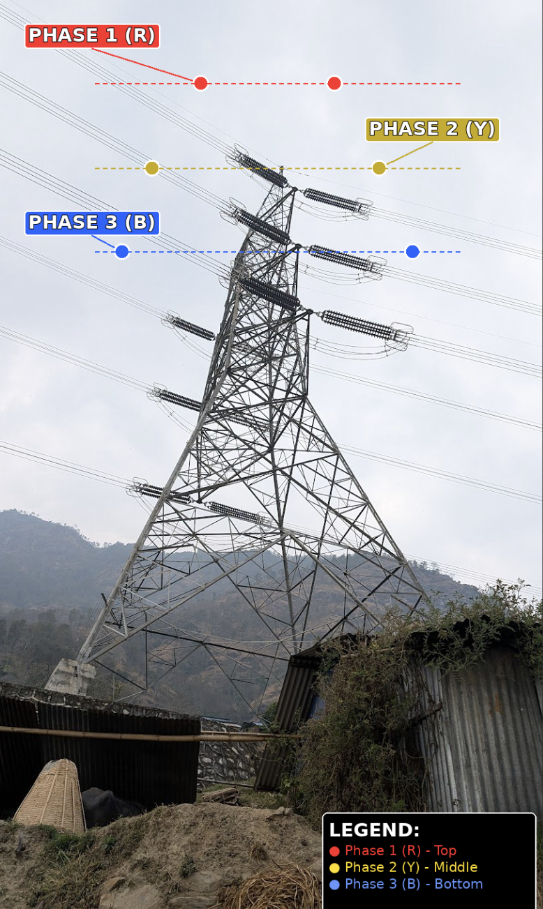
Q: What are the disc-like or ring-like structures where the wires connect to the tower?
A: Those are insulator strings (or insulator assemblies). They are made of porcelain, glass, or modern composite polymer materials. Their purpose is to electrically isolate the high-voltage conductors from the grounded metal tower. The number of discs in a string is proportional to the voltage: higher voltages require more insulator discs to prevent the electricity from arcing (jumping) across to the tower. For a 400 kV line, you might see 20 or more insulator discs in a single string.
Q: Is it possible to estimate the voltage of a transmission line just by looking at the tower?
A: Yes, roughly. Higher-voltage lines have taller towers with wider spacing between conductors, longer insulator strings (more discs), and often thicker or bundled conductors. A 66 kV line might have relatively short insulators and modest spacing, while a 400 kV line will have very long insulator strings, wide cross-arms, and sometimes bundled conductors (two or more wires per phase held together by spacers). With experience, you can estimate the voltage class with reasonable accuracy by observing these features.
Q: What is the single wire at the very top of the transmission tower, above all the power conductors?
A: That is the ground wire, also called the shield wire, earth wire, or static wire. It does not carry power. Its purpose is lightning protection. It sits at the highest point of the tower to intercept lightning strikes before they can hit the power conductors below. When lightning strikes the ground wire, the current flows safely down the tower structure into the earth through the tower’s grounding system. In modern installations, this ground wire is often an OPGW (Optical Ground Wire), which contains optical fibers inside it for communication purposes — serving a dual function of lightning protection and data transmission.
Q: On the tower I photographed, I counted six separate groups of three wires each. Why so many, if one group of three (one three-phase circuit) should be sufficient?
A: Each group of three wires represents one three-phase circuit. Having multiple circuits (in your case, likely two double-circuit configurations or six individual circuits) on the same tower serves several purposes. First, capacity: each circuit has a maximum power-carrying capacity. Multiple circuits multiply the total capacity of the corridor. Second, redundancy and reliability: if one circuit fails or needs maintenance, the others continue operating, preventing total power loss. Third, serving different routes: different circuits on the same tower may be routed to different substations or serve different customers. Fourth, future-proofing: towers are often built to carry more circuits than initially needed, anticipating future generation projects (like your example of a river cascade with projects being developed over 10–15 years). Building the tower infrastructure once and loading it gradually over time is more economical than building new towers later.
Q: Why not just use one set of thicker, more conductive wires instead of multiple sets?
A: There are several practical reasons. Beyond a certain thickness, a single conductor becomes impractical due to weight, wind loading, and a phenomenon called the ‘skin effect’ (in AC systems, current tends to flow near the surface of a conductor, so making it thicker has diminishing returns). Multiple smaller conductors per phase (bundled conductors) are actually more efficient than one thick conductor. Additionally, separate circuits provide redundancy — if one set fails, the others keep working. A single super-thick wire offers no redundancy. Finally, different circuits may operate at different voltages or serve different routing needs, which is impossible with a single conductor set.
Q: What are the standard transmission voltage levels used in Nepal?
A: Nepal’s transmission network currently operates at several voltage levels: 66 kV (older, shorter-distance lines), 132 kV (the traditional backbone of Nepal’s grid), 220 kV (newer, higher-capacity lines), and 400 kV (the highest voltage level, used for bulk power transfer, including the planned East-West transmission corridor and cross-border interconnections with India). The global range for transmission voltages extends from about 69 kV to 1,100 kV (Ultra-High Voltage in China), but Nepal’s grid primarily operates within the 66–400 kV range.
Q: What are the brightly colored ball-shaped objects sometimes attached to transmission lines?
A: Those are aviation marker balls (also called aerial marker spheres or visibility markers). They are typically bright orange, red, white, or yellow, and about 30–90 cm in diameter. They are installed on power lines in areas where low-flying aircraft might be at risk — near airports, heliports, river crossings, valleys, or anywhere the lines are particularly difficult to see. They serve no electrical function; their sole purpose is visual warning for pilots.
Q: How does the economics of transmission work when generation projects are developed in phases over many years?
A: Transmission infrastructure is typically built with a long-term planning horizon (20–40 years). The common approach is to build the towers and line infrastructure to their ultimate design capacity upfront, even if the initial loading is low. This is because the civil works (foundations, towers, right-of-way acquisition) represent a large portion of the cost and are extremely disruptive and expensive to redo later. The conductors themselves can sometimes be installed in phases — for example, stringing only one circuit initially and adding the second circuit later as more generation comes online. This phased approach spreads the financial burden while avoiding the much higher cost of building entirely new corridors later.
Chapter 10: Power Distribution and Load Management
Q: In a real power system, how is the balance between generation and load maintained in real-time?
A: The balance is maintained through a hierarchy of control mechanisms operating at different time scales. Primary control (governor response) acts within seconds: the turbine governor detects frequency deviations and automatically adjusts the water or fuel flow. If demand drops, frequency rises, and the governor reduces input. Secondary control (Automatic Generation Control, or AGC) acts within minutes: a centralized system sends signals to generators to fine-tune their output based on the measured frequency and power flows across the grid. Tertiary control (economic dispatch and scheduling) acts over hours: operators and algorithms schedule which generators to run and at what output, based on demand forecasts, fuel costs, and maintenance needs. Protective devices (dump loads, load shedding) act as emergency measures. Dump loads absorb excess power when generation cannot be reduced quickly enough. Load shedding disconnects non-critical loads when demand exceeds available generation (a practice Nepal has historically relied on heavily).
Q: Does the Nepal Electricity Authority use automated systems, or do they manually call generators to adjust output?
A: Nepal uses a mix. Larger, grid-connected hydropower plants (especially those operated by NEA or large independent power producers) increasingly have automated governor and excitation control systems, often integrated with NEA’s SCADA system for remote monitoring and some degree of remote control. Smaller micro-hydro plants in remote areas often rely on simpler electronic load controllers (ELCs) that automatically divert excess power to dump loads (like water heaters or air heaters) to maintain frequency. Human operators still play a significant role, particularly in coordinating between different generators, managing outages, and making dispatching decisions. The system is not fully automated by developed-country standards, but it is modernizing.
Q: What are ‘dynamic loads’ or ‘dump loads’ in the context of power systems?
A: In the context of small power systems and microgrids, a dump load (also called a ballast load or diversion load) is a device that absorbs excess electrical energy when the consumer demand is lower than the generation output. The most common dump loads are resistive heaters (water heaters, room heaters, or simply large resistor banks) that convert excess electricity into heat. An Electronic Load Controller (ELC) continuously measures the system frequency. If the frequency rises (indicating excess generation), the ELC diverts power to the dump load. If the frequency drops (indicating the load is too high), the ELC reduces the dump load. This keeps the frequency stable without needing to adjust the turbine itself, which is especially useful in small hydro systems where turbine control is simpler.
Chapter 11: SCADA and Grid Communication Systems
Q: What is SCADA, and how does it work in the context of Nepal’s power system?
A: SCADA stands for Supervisory Control and Data Acquisition. It is a centralized system that allows operators to monitor and control a distributed network of equipment from a single location. In Nepal, the Nepal Electricity Authority (NEA) operates its central SCADA system from the Load Dispatch Centre (LDC) in Kathmandu. The system works as follows: sensors and Remote Terminal Units (RTUs) at substations and power plants collect real-time data such as voltage, current, frequency, power flow, breaker status, and transformer tap positions. This data is transmitted over a dedicated communication network to the central SCADA server. Operators at the LDC can view the entire grid’s status on screens, receive alarms for abnormal conditions, and send remote commands (like opening or closing circuit breakers, adjusting transformer taps, or changing generator setpoints). The communication protocol used is typically IEC 60870-5, which is the international standard for telecontrol in power systems.
Q: What communication infrastructure does the SCADA system use? Does it use normal telecom networks like Nepal Telecom?
A: No. NEA’s core SCADA communication runs on a dedicated, private network that is separate from public telecom infrastructure. This is for reliability (public networks can be congested or disrupted) and security (grid control commands must be protected from unauthorized access). The primary communication technologies used are optical fiber cables, typically ADSS (All-Dielectric Self-Supporting) cables mounted on transmission towers or OPGW (Optical Ground Wire) integrated into the top ground wire of transmission lines. In areas where fiber is not yet installed or is impractical, microwave radio links are used as the communication medium. These are point-to-point line-of-sight radio links between towers, providing high-bandwidth digital communication without needing physical cables. The backbone is fiber for major corridors, with microwave for remote or mountainous locations. This is standard practice globally — utilities in Europe, North America, and Asia all maintain separate, dedicated communication networks for their grid operations.
Q: Are there really optical fibers running along those massive high-voltage transmission towers?
A: Yes. This is a well-established global practice and is done in Nepal as well. There are two common methods. OPGW (Optical Ground Wire) embeds optical fibers inside the topmost ground/shield wire of the transmission tower. This serves the dual purpose of lightning protection and data communication. ADSS (All-Dielectric Self-Supporting) cable is a lightweight fiber-optic cable that is strung separately on the transmission towers, typically below the power conductors. It contains no metal, so it is not affected by the electromagnetic fields of the power lines. Both methods take advantage of the existing transmission tower infrastructure (right-of-way, towers, maintenance access) to deploy communication fiber at much lower cost than building a separate fiber route.
Q: Is there any sharing of fiber infrastructure between electricity utilities and telecom companies?
A: Yes, this is increasingly common. Utilities that have installed fiber along their transmission lines often have excess capacity (called ‘dark fiber’ — fiber strands that are installed but not yet in use). They can lease this dark fiber to telecom operators, generating additional revenue. In Nepal, there are examples of cooperation between NEA and Nepal Telecom for fiber sharing along certain corridors. However, the utility always keeps its core grid communication on separate, dedicated fibers (or separate logical channels with encryption) to ensure that grid operations are never compromised by telecom traffic. The sharing is of the physical infrastructure (the fiber cable), not of the operational communication channels.
Note: This practice of utility fiber-telecom sharing is an increasingly important strategy in developing countries, where it can significantly reduce the cost of expanding broadband connectivity to rural and remote areas by leveraging existing electricity infrastructure.
Chapter 12: Birds, Humans, and Electrical Shock on Transmission Lines
Q: Why don’t birds get electrocuted when they sit on high-voltage power lines?
A: When a bird perches on a single power line, both of its feet are on the same conductor, at the same voltage. Since there is no voltage difference across the bird’s body, no current flows through it. It is the same principle as a person touching one terminal of a battery — nothing happens because there is no complete circuit. The bird is essentially at the same electrical potential as the wire. The danger arises only if the bird simultaneously touches two conductors at different voltages, or touches a conductor and a grounded structure (like the metal tower). Large birds with wide wingspans (eagles, storks) are at risk for exactly this reason — their wings can bridge the gap between a conductor and a grounded cross-arm, creating a fatal voltage difference.
Q: If a human were suspended in mid-air (like a bird) and touched only one power line, would they be safe?
A: In theory, yes. If a person were perfectly isolated from the ground and all other conductors — like a bird perching on a single wire — no current would flow through their body because there would be no voltage difference. Utility line workers actually do this routinely: ‘bare-hand’ or ‘live-line’ workers are brought close to high-voltage lines in insulated buckets or helicopters. They touch the energized conductor deliberately, and once their body is at the same potential as the line, they can safely work on it. The critical requirement is complete isolation from ground and any other potential. In practice, achieving this isolation for an untrained person is extremely dangerous because even a small path to ground (through a tool, a rope, moisture, or proximity to the tower) could complete the circuit and be fatal.
Q: Does rain, humidity, or wind increase the risk for birds on power lines?
A: In extreme conditions, yes, the risk can increase. Heavy rain can create a thin film of water on insulator surfaces, reducing their insulating effectiveness and potentially allowing current to ‘track’ along wet surfaces. Wind can cause birds to shift or spread their wings, potentially bridging the gap between a conductor and the tower. However, for birds sitting on a single wire in normal rain, the risk increase is minimal because the bird’s body is still at the same potential as the wire. The rain does not create a path to a different voltage. The real danger from wet conditions is more relevant to the insulator performance and the risk of flashover (an arc jumping across the insulator surface), which affects the power system rather than the bird specifically.
Q: If electricity from a rain-wet bird tried to ‘escape’ into the air, would the bird get shocked even without a path to ground?
A: No. Electricity requires a complete circuit to flow. Air is an excellent insulator (that’s why transmission lines can operate at hundreds of thousands of volts in open air). Current does not ‘leak’ from a conductor into the surrounding air under normal conditions. Even in rain, the air gap between the wire and the ground (which is many meters on transmission towers) provides far more than enough insulation. The bird would only be at risk if a conductive path formed between the wire it is sitting on and another object at a different voltage — which rain alone, at the scale of a bird, does not create.